Surface wiring systems are used to extend electric current and power from existing outlets or fixtures to a new location, without having to tear up floors or cut into walls or ceilings. It is important to realize that surface wiring is only an acceptable practice indoors, and poses many safety concerns when implemented outside. In surface-wiring systems, standard 120-volt wires are installed in metal or plastic channels (raceways), which are fastened to interior surfaces at baseboards, under wall cabinets or across finished walls, floors or ceilings. Networking, coaxial cable, communications, audio system and other low-voltage wiring may also be installed, but wire must never be in the same channel or terminate in a wiring box with 120-volt wires. An add-on installation usually taps into an existing outlet (receptacle or light) and extends power to a variety of surface-mounted devices (switches or receptacles) or outlet boxes.
Typical applications include: temporary wiring (lowering a light switch for young children or adapting a space for a home office); wiring for concrete or cement block walled basements, garages or shops (dry locations only); multiple receptacles for kitchen counters; or convenience receptacles or outlets for lights, a ceiling fan or other electrical fixture anywhere in the home. Metal systems are functional, impact resistant and a good choice for workshops and the like. Decorative plastic systems are, by design, usually better looking and easier to install, and rewire if changes are required in the future.
The skills needed are minimal, but do assume a basic understanding of how your electrical system works, basic wiring skills and how to wire switches, receptacle and lights.
To begin, draw a simple plan that uses material efficiently and/or is least noticeable, depending on the location. At the service panel, identify the capacity of the existing circuit (usually either 15 or 20 amps). Then verify that it can handle additional outlets: shut off power to the circuit by tripping the breaker or pulling the fuse; then use a continuity tester to identify all outlets (receptacles and lights) that are on the circuit. Allowing 1.5 amps for each outlet, a 15-amp circuit (as determined by the fuse/breaker capacity and minimum No.14 awg wire size) will handle ten outlets, and a 20-amp circuit will accept thirteen outlets. Always match new wire gauges to the existing gauge wire you are extending from when attempting any surface-wiring project. Any electrical outlets that will be within 6 feet of a water source must utilize a Ground Fault Circuit Interrupter (GFCI). A GFCI receptacle will shut off the circuit if it detects that current has begun flowing to an unwanted destination and minimize the risk of electric shock.
The plan should also list the number and type of outlets (receptacles, lights), both existing and proposed, and the location (kitchen, basement, etc.) involved. Review those plans with a licensed electrician and/or an electrical inspector for your locality. Discuss local electrical codes that govern what must be done, who can do the work, and if inspections are required or advised.
Next, obtain the necessary supplies needed from an online electrical supply store or your local hardware retailer to prepare a list of materials, including raceways, connecting fittings, wiring connectors and wiring boxes; also gather equal lengths of black, white and green Nos.12 or 14 wire and any needed devices. Make sure to always use Thermoplastic High Heat-resistant Nylon (THHN) coated wires. NEVER use romex type (or any other cable sheath wires) for a surface-wiring project, as they are simply not designed to handle the sharp bends and crimps encountered in a raceway elbow. To fasten raceways you'll need appropriate fasteners: For wood (or drywall at wood stud locations) use flat-head wood screws; for drywall, use plastic shields with flat-head wood screws; for plaster, brick, concrete or masonry, use plastic shields and flat-head sheet metal screws; and for tile, use toggle bolts or plastic shields with flat-head wood screws. Finally, collect the required electrical tools: standard and long nose pliers, slotted and Phillips head screwdrivers, wire stripper, utility knife, fine-tooth hacksaw and fine tooth file. An electric drill/driver may also be required.
Transfer your plan to the wall using a level and pencil to mark raceway, fitting and wiring box locations. SHUT OFF THE POWER to the circuit at the service panel and VERIFY THERE IS NO POWER at the existing outlet (use a voltage tester or plug in an electric tool/lamp that you know is in working order). Remove the outlet cover plate and attach an extension plate with screws provided. Then loosely install all other mounting plates, using the appropriate fasteners. Measure and cut raceway with a fine-tooth hacksaw. Connect the raceway to mounting plates and the surface, attaching fittings, such as elbows and T's, where required. (Depending on the system, the raceway may fasten directly to the wall or to preinstalled clips.) Then finish securing mounting plates and install wiring boxes (extension frames) to the mounting plates. Follow manufacturer’s instructions regarding notching the boxes to accept the raceway. With metal systems, make sure you file any sharp edges after cutting and use bushings as recommended.
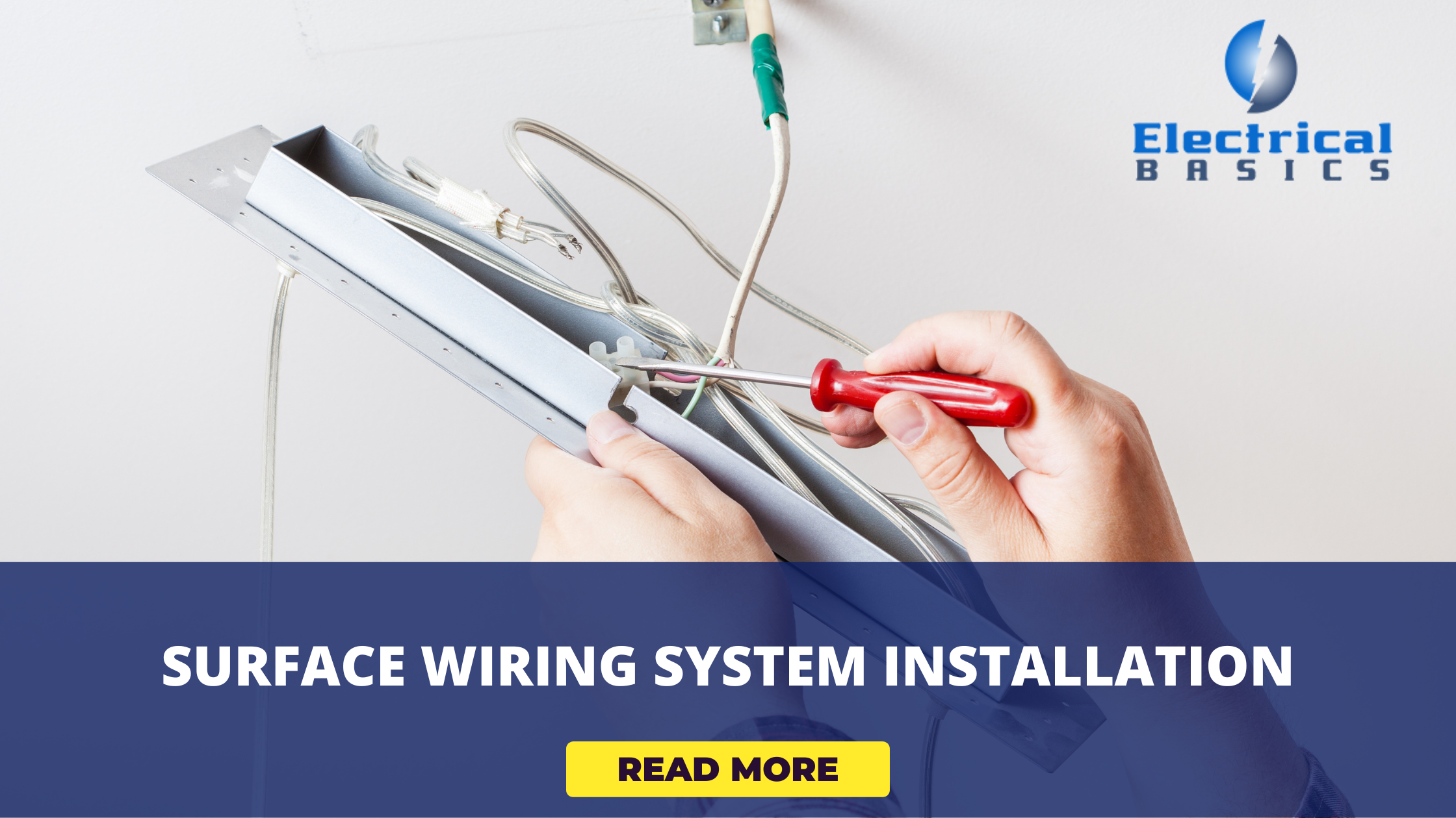
Finally, begin wiring. Fish three lengths of wire between each box location, allowing a minimum of 8 inches extra at each end for splices. Rewire the existing source outlet creating a pigtail connection for hot, neutral and ground wires; connect the corresponding wires in the new surface system and wire all new devices and fixtures. Perform the continuity tests to confirm proper grounding and polarity within the new system, before restoring power.